A printed circuit board can look like a finished product long before it can power a device. That gap trips up budgets, timelines, supplier selection, and quality plans. Teams often treat the board as a single line item, then get surprised when quotes, lead times, and responsibilities shift mid project.
In practice, PCB Assembly vs. Fabrication signals two distinct stages that require different tooling, controls, and decision points. Many electronics teams, including those that work with Beyonics, plan better outcomes by separating these stages early, then aligning specs, files, test strategy, and acceptance criteria to each step.
What PCB Fabrication Produces and Why It Matters

Fabrication creates the bare board. Think copper layers, insulating laminate, vias, solder mask, silkscreen, and surface finishes. This stage turns design files into a physical platform that can accept components. Fabricators focus on geometry, materials, and process tolerances. They care about trace widths, spacing, drill sizes, impedance targets, stack up design, and how the board will survive heat, vibration, humidity, and handling.
Business impact shows up fast. Material choice and stack up drive cost and lead time. A controlled impedance board, a high layer count, or tight annular ring requirements can push the fabricator into slower, higher risk process windows. Small spec changes can trigger a different laminate, a different finish, or different drilling and plating steps. Each change can affect yield and schedule. That makes fabrication the place to lock down manufacturability early, not after a prototype fails.
What PCB Assembly Delivers and What Changes in Production
Assembly populates that bare board with components and turns it into a functional electronic unit. Teams place SMT parts, mount through hole components, run reflow or wave solder, and inspect joints. Assembly also includes programming, cleaning, conformal coating, selective soldering, and mechanical integration when the product needs those steps. The assembler manages line setup, feeders, stencils, profiles, work instructions, and operator training.
Production pressure rises here because variability comes from many directions. Component packaging, moisture sensitivity, part substitutions, and paste deposition all affect results. Even a “simple” board can fail if the BOM includes a hard to place connector, a fine pitch IC, or parts that shift during reflow. That is why assembly planning lives and dies by accurate CAD data, a clean BOM, reliable sourcing, and a realistic test strategy. A board that fabricates perfectly can still fail in assembly if design choices ignore placement keep outs, polarity markings, or rework access.
Files, Data Packages, and Hand Off Points That Reduce Risk
Fabrication depends on a manufacturing data set that describes the board itself. Teams usually provide Gerbers or ODB++, drill files, a stack up drawing, impedance notes, fab drawings, and any special requirements for plating, finish, or panelization. Clear notes prevent costly interpretation. If the fabricator guesses, the board may still “match the files” while missing your intent for thickness, copper weight, or controlled impedance.
Assembly relies on a different package. The assembler needs a BOM with approved alternates, pick and place centroid data, assembly drawings, polarity and orientation notes, and an inspection plan. They also need programming files and test requirements. Many delays come from gaps between design intent and line reality, such as missing reference designators, mismatched footprints, or a BOM that lists parts without manufacturer part numbers. Strong hand offs replace back and forth emails with a stable source of truth that both purchasing and production can use.
Quality Control and Testing: Different Goals, Different Metrics
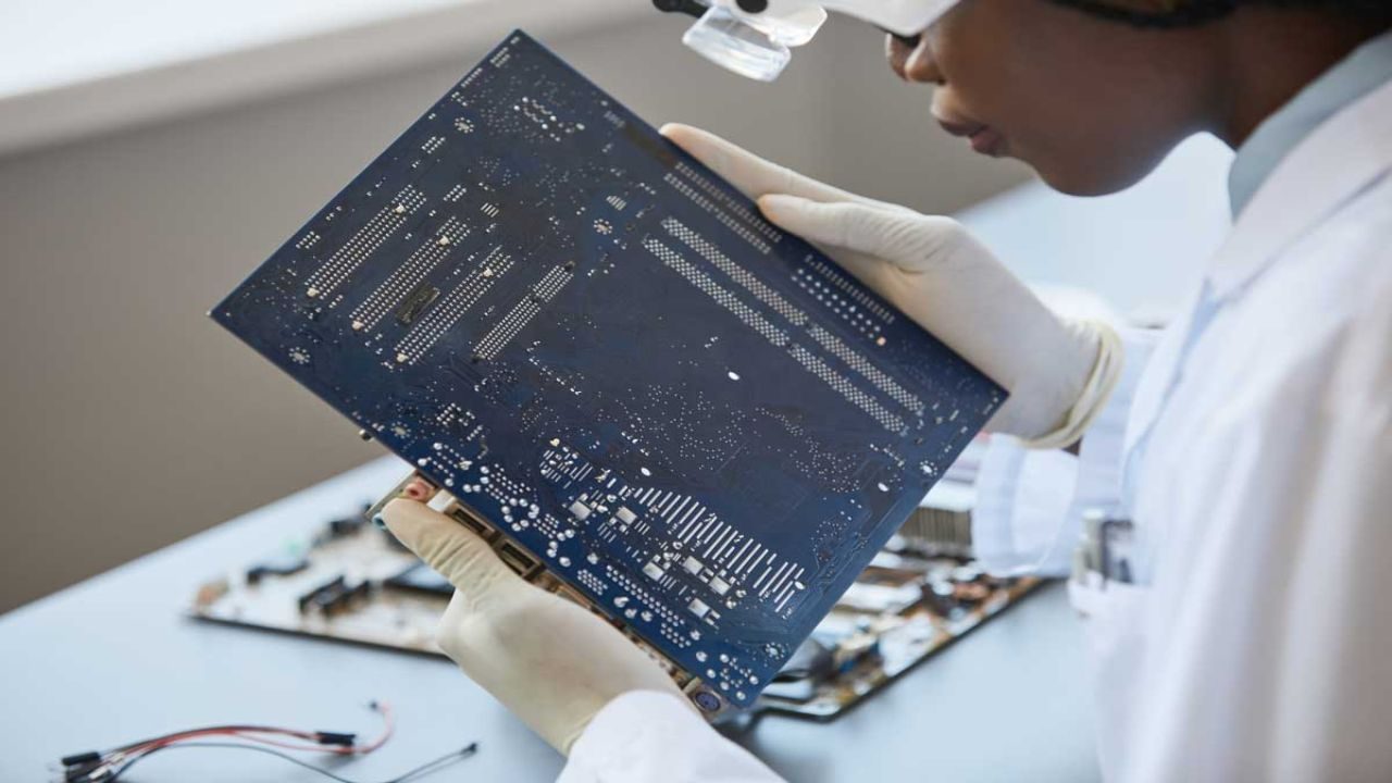
Fabrication quality aims to confirm the board matches electrical and mechanical requirements. Common controls include AOI for layer imaging, impedance coupons, microsection analysis, solder mask alignment checks, and electrical test for opens and shorts. These checks protect against hidden defects like under plated vias, over etched traces, or inner layer registration issues. The goal stays simple: deliver a reliable platform for assembly.
Assembly quality targets functional performance and reliable solder joints. Inspectors look for tombstoning, bridging, insufficient solder, cold joints, and component damage. They use SPI, AOI, X ray for BGAs, and in circuit testing or functional testing where feasible. A smart plan ties inspection to risk. For example, a board with fine pitch parts benefits from tighter AOI rules and X ray sampling. A board with connectors and heavy components benefits from mechanical stress checks and torque guidance. Quality becomes cheaper when teams set these expectations before the first build, not after failures show up in the field.
Cost and Lead Time Drivers You Can Control Early
Fabrication cost tends to rise with complexity. More layers, tighter tolerances, special materials, heavier copper, and advanced finishes all add time and scrap risk. Panelization choices matter too. A board that wastes panel space costs more per unit even if the design looks small. Lead time can stretch when the fabricator needs uncommon laminate or must hit strict impedance windows that require extra validation.
Assembly cost depends on component count, placement difficulty, and sourcing stability. Fine pitch packages, double sided placement, mixed technology builds, or selective solder steps add labor and setup time. Frequent design revisions drive costs as well because each revision forces new stencils, new programming, and fresh validation. To control spend, teams should simplify footprints when possible, qualify alternates early, and design for accessible testing. Small design choices, like adding test points or improving silkscreen polarity marks, can save hours of troubleshooting at scale.
How to Choose the Right Partner Mix for Your Product Stage
Early prototypes often succeed with separate specialists. A dedicated fabricator can optimize board build quality while an assembler focuses on placement and rework readiness. This setup also lets you swap one vendor without disrupting the other if performance falls short. It works well when engineering changes happen often and teams want tight feedback loops on both the bare board and the build process.
As volume grows, many businesses prefer tighter integration. A single source that coordinates bare boards, parts procurement, and build execution can reduce hand off friction and speed up issue resolution. That approach helps when schedules get aggressive and procurement risk rises. Still, buyers should verify where work happens, how the partner manages traceability, and who owns final acceptance. The best choice comes from your priorities: speed to market, cost per unit, regulatory demands, and the level of design maturity. When teams match supplier structure to product stage, they avoid avoidable rebuilds and keep launches predictable.